● Accepted — MICCAI CLIP 2026

Intraoperative Fully Automatic Registration of Fluoroscopic Image Pair: Cadaveric Evaluation

Presenting Thursday, 1 October 2026  ·  Room Churchill  ·  Strasbourg Convention Center, France

Sandeep1*, Vishwanath Reddy B1*, Abhilash Chakkaravarthy1*, Vivek Maik1, Aparna Purayath1, Suhail Ansari T. A.1, Manojkumar Lakshmanan1, Mohanasankar Sivaprakasam2†

1 Healthcare Technology Innovation Centre, IIT Madras, India  ·  2 Indian Institute of Technology (IIT) Madras, India
*Equal contribution  ·  †Corresponding author

Overview

Abstract

Pedicle screw placement remains a challenge in minimally invasive spine surgery (MISS), largely because mobile C-Arms lack pre-acquisition geometric calibration and exhibit position-dependent imaging distortion. In this paper, we propose a fully automatic 2D C-Arm fluoroscopic image registration system that requires only an anterior-posterior (AP) and lateral (LA) image with overlaid fiducial markers from a custom-designed calibration drum — a rigid frame attached to the C-Arm with metal sphere fiducials distributed across two non-coplanar planes. The framework performs automatic fiducial detection, distortion correction, and camera calibration. Evaluated on phantom, cadaveric, and patient data, the pipeline achieves sub-pixel reprojection error (RPE) and clinically acceptable accuracy, yielding Grades A and B on the Gertzbein–Robbins (GR) scale.
Fluoroscopic calibration Intraoperative registration Pedicle screw navigation Image-guided surgery Device-agnostic deployment Cadaveric validation
Introduction

Why Automatic Registration Matters

Pedicle screw placement in MISS is highly precision-demanding — even a slight trajectory deviation can cause serious spinal injury or nerve root damage. Mobile C-Arm fluoroscopy remains the dominant intraoperative modality for MISS. Without a CT modality, C-Arm fluoroscopy alone is responsible for guiding the MISS pedicle placement. The C-Arm imaging for AP and LA shots needs to be registered to the intraoperative patient anatomy for the MISS surgery to be accurate. Existing calibration approaches each fall short:

i

Manual methods

Surgeons manually click fiducial points in every image — time-consuming, causing a 5–15 minute disruption per case.

ii

Device-specific methods

Rely on factory distortion maps or isocentric C-Arm geometry, making them incompatible with the diverse range of C-Arm models from different manufacturers.

iii

Learning-based methods

Achieve sub-pixel landmark localisation but require large C-Arm-specific training sets and offer no mathematical guarantees on geometric accuracy.

This work addresses all three drawbacks with a five-stage, fully automatic pipeline anchored to a Coordinate Measuring Machine (CMM)–characterised multi-faceted calibration drum, deployable on any C-Arm unit without hardware or software modification.

Methodology

A Five-Stage, Device-Agnostic Pipeline

Anchored to a CMM-characterised multi-faceted calibration drum, deployable on any C-Arm unit without hardware or software modification.

1

Preprocessing

AP & LA C-Arm shots are contrast-enhanced and noise-filtered against the multi-faceted calibration drum.

2

Blob Detection & Correction

Fiducials are detected, outliers removed, distortion estimated, and positions corrected via thin-plate spline warping.

3

Point Labeling

Positional fiducials anchor an angular reference so every calibration fiducial is uniquely ordered.

4

Camera Calibration

2D–3D correspondences drive DLT + Levenberg–Marquardt refinement to estimate P = K[R | t].

5

Accuracy Validation

Optically tracked tool tip is projected into AP/LA image space; target registration error is validated ≤ 1 mm.
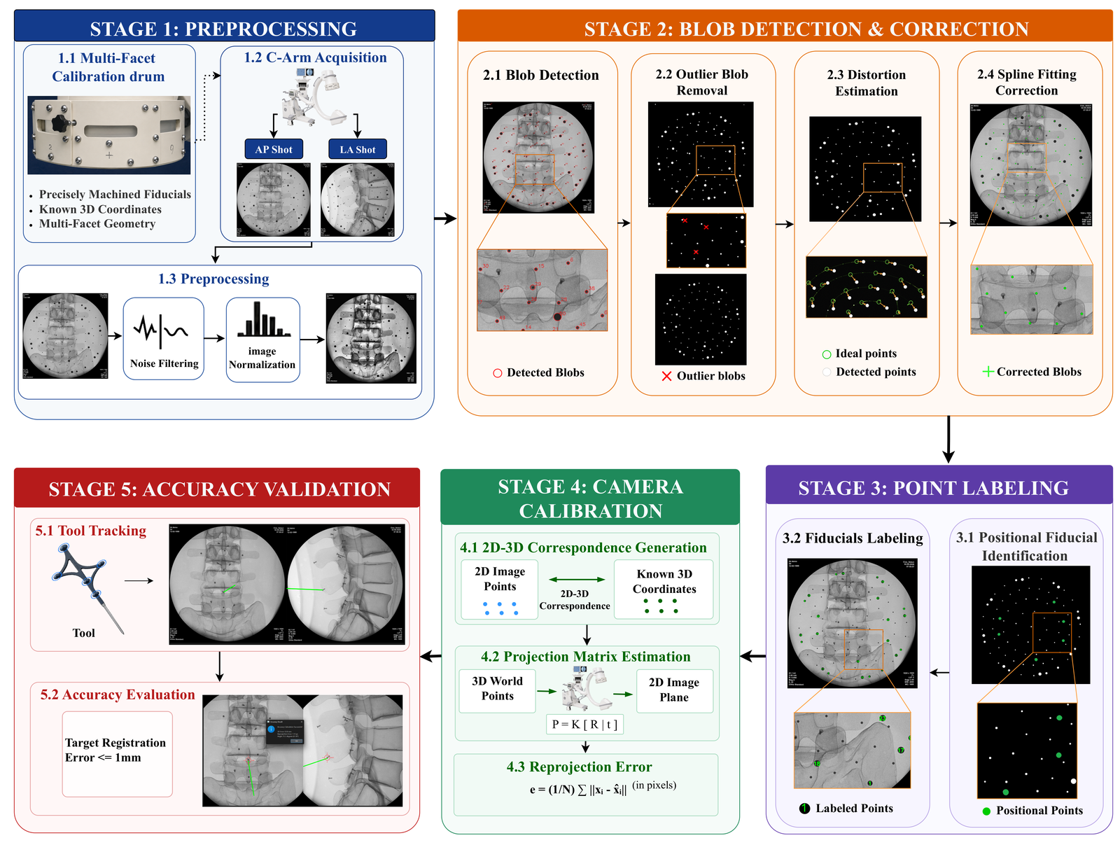
Full five-stage registration pipeline diagram
Fig. 2. The fully automatic device-agnostic registration pipeline. Processing flows left-to-right through preprocessing and distortion correction, then right-to-left through point labeling, calibration, and validation.

2.1  Multi-Faceted Calibration Drum

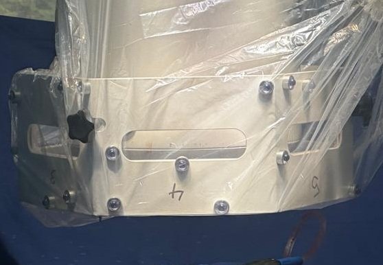
The drum carries metallic spherical fiducials embedded. The ground truth of the calibration drum is derived from the 3D positions of its fiducial markers measured by a Coordinate Measuring Machine (CMM), which directly determines the baseline accuracy. The dual-plane fiducial configuration of the drum ensures a geometrically stable estimation of the projection matrix. The fiducials are arranged in a dual-plane layout which provides the required depth variation that a single-plane design lacks, enabling accurate estimation of both intrinsic and extrinsic camera parameters. The drum's 86 physical fiducials split into three functional groups:

17 calibration fiducials — 2D–3D correspondences 64 distortion fiducials — evaluate & remove distortion 5 positional fiducials — angular reference for labeling

The multi-faceted design ensures fiducials remain visible to the camera irrespective of the drum's orientation, for reliable tracking in all C-Arm poses.
Custom-designed multi-faceted calibration drum
Fig. 1. Custom-designed multi-faceted calibration drum.

2.2  Fiducial Detection

The C-Arm image is pre-processed for contrast enhancement and noise removal. A dedicated fiducial detection module then identifies fiducials by size, circularity, and convexity, rejecting noise artifacts and elongated anatomical structures. Each candidate undergoes contour-based shape verification to minimise false positives; images with insufficient fiducials are rejected outright.

2.3  Distortion Correction

C-Arm fluoroscopic images typically exhibit geometric distortions — pincushion and S-distortion — that displace fiducials from their true locations. In order to apply distortion correction, the detected fiducials are grouped into four concentric rings corresponding to the calibration drum using Euclidean distance clustering. Because magnification varies with C-Arm zoom and source-to-detector distance, a millimeter-to-pixel scale factor is estimated per image by minimizing cumulative radial alignment error. Matched correspondences then drive an iterative thin-plate spline (TPS) warp that computes the corrected fiducial positions.

2.4  Fiducial Labeling

Each corrected fiducial is ordered sequentially to establish fiducial-to-CMM correspondence. Fiducials are separated into planes by clustering radial distance from the image center, yielding distinct ring groups. Each ring group is then ordered by comparing angular position against positional fiducials and a pre-computed angular reference, yielding a fully ordered set of calibration fiducials.
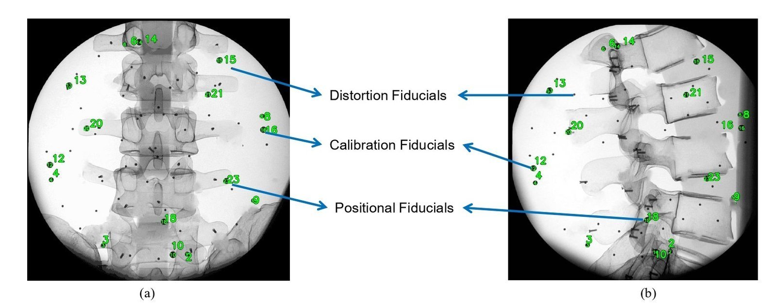
Automatic fiducial labeling on AP and LA views
Fig. 3. Automatic fiducial labeling on AP and LA views — Distortion, Calibration, and Positional fiducials.

2.5  Camera Calibration

Correspondences between the ordered 2D fiducial points and known 3D CMM points are resolved via the Direct Linear Transform (DLT) with Levenberg–Marquardt refinement, producing the 3×4 projection matrix:

P = K [ R | t ]

The resulting projection matrices support intraoperative MISS across all acquired views with consistent sub-pixel reprojection error. Validation projects the optically tracked tool tip from patient reference space into AP and LA image space and computes the target registration error (TRE) against known ground truth:
e = (1/N) ∑ᵢ ‖xᵢ − x̂ᵢ‖  (pixels)
Experiments

Results

To fully assess geometric accuracy and clinical feasibility, experiments included a controlled phantom study to determine baseline geometric accuracy, a cadaveric study with pedicle screw placement, and an evaluation of live patient data to assess algorithmic performance under surgical setups. The registration pipeline was implemented in two builds: a CPP build for real-time intraoperative low-latency surgical use, and a MATLAB build serving as an offline prototyping and validation benchmark used to verify algorithmic correctness independently of real-time constraints. All studies were approved by the institutional ethics committee, with informed consent obtained from all participants.

0.90 mm
Mean 3D registration error — phantom study
94%
Grade A+B acceptance — cadaveric study (both methods)
90.5%
Grade A+B acceptance — 2D fluoro registration
25
Pedicle screws placed across 7 live patient cases

3.1  Blob Detection Reliability

Achieving accurate 2D–2D registration crucially depends on precisely locating the calibration drum's fiducials prior to estimating its camera matrix. The fiducial detection module was evaluated by performing blob detection on a large and diverse dataset of 564 fluoroscopic images, spanning both phantom and cadaveric scans. Both the C++ and MATLAB builds consistently exceeded the 86-fiducial ground truth (calibration 17 + distortion 64 + positional 5) of the calibration drum, demonstrating adequate sensitivity even in the presence of anatomical occlusion and image-intensifier noise.

Table 1 — Fiducial detection: C++ vs. MATLAB benchmark (564 images, 86 physical fiducials)
ImplementationMean ± StdMinMaxTime Taken
MATLAB91.54 ± 17.67261326.4 sec
C++87.82 ± 16.20171810.8 sec
Ground Truth (Drum)86———

3.2  Phantom Study

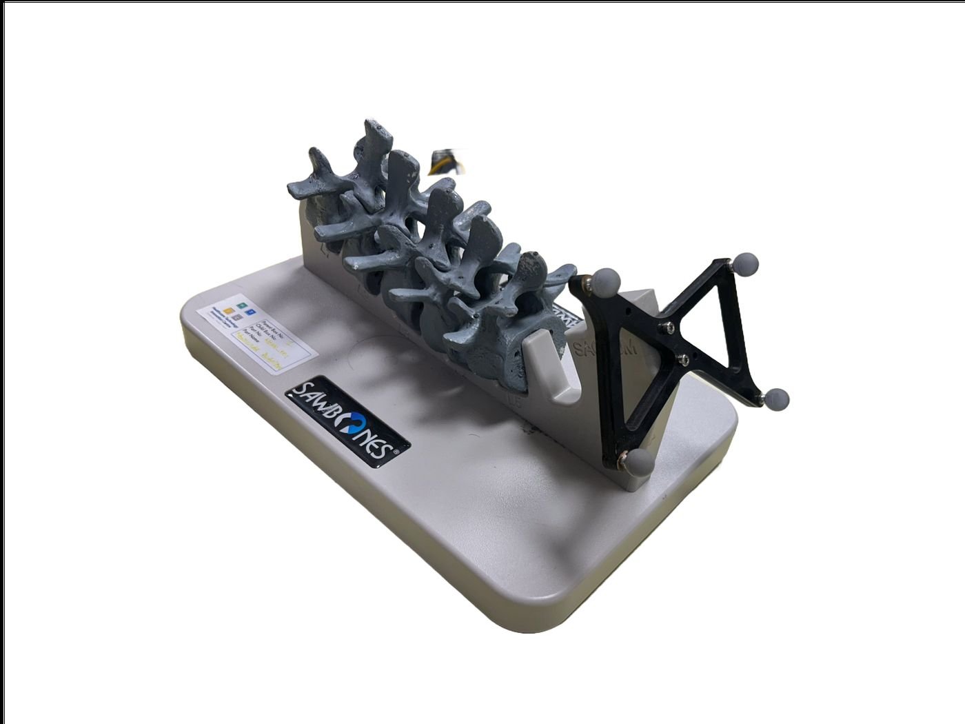
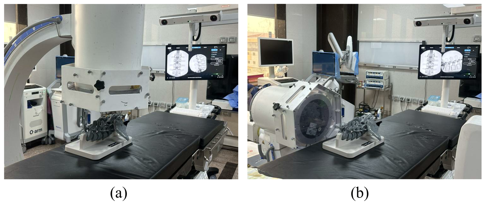
Experiments were performed on Sawbones lumbar spine phantom models in a controlled operating theater setup (Fig. 4).

AP and Lateral C-Arm experimental setup
Fig. 4. Experimental setups: (a) AP C-Arm setup, (b) Lateral C-Arm setup.

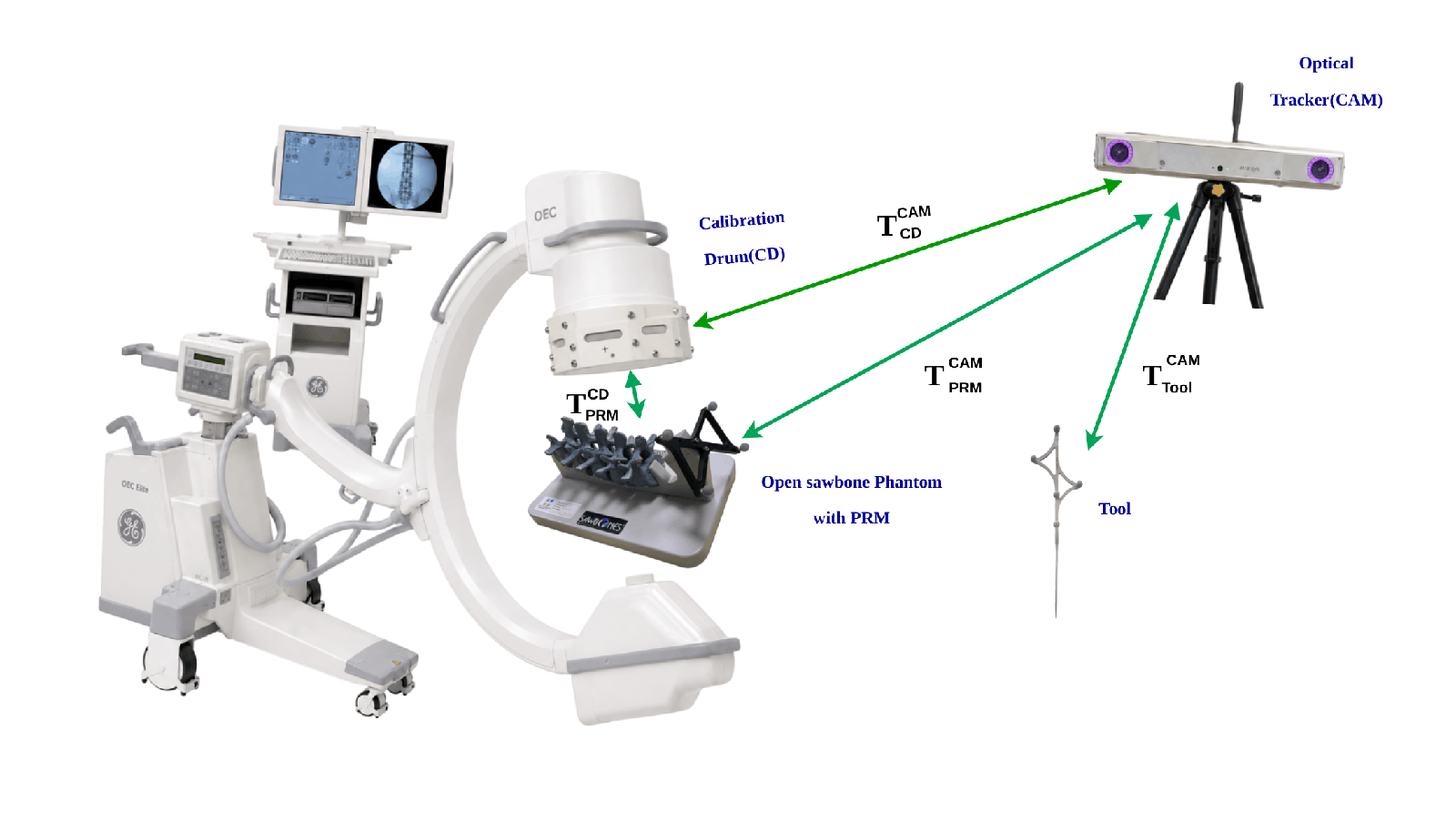
To establish the ground-truth spatial relationship, an optical tracking camera captured real-time transformations from the camera to the patient reference marker (PRM) rigidly attached to the phantom, from the camera to the calibration drum's IR markers, and from the camera to surgical tool markers used to mark the target location on spinal vertebrae (Fig. 5).

Optical tracking setup with calibration drum and surgical tool
Fig. 5. Optical tracking camera, patient reference frame, calibration drum, and surgical tool coordinate transforms.

The spatial relationship between the C-Arm image space and the patient reference space was established during image acquisition via a transformation that maps the calibration drum coordinate frame to the patient reference frame through the camera frame:

TPRMCD = (TCDCAM)−1 · TPRMCAM

Since the tracking camera observes only the IR markers mounted on the tool handle, the physical tool tip position cannot be measured directly. Instead, a one-time pivot calibration was performed prior to the experiment; the tool tip was held stationary in a fixed pivot while the handle was rotated through multiple orientations. From these observations, the rigid offset TTipTool between the marker frame and the tip was computed and stored. During the experiment, this pre-calibrated offset was applied to every tracked handle pose to recover the tip position. The real-time tool tip position in patient space was then continuously computed as:

TTipPRM = (TPRMCAM)−1 · TToolCAM · TTipTool

To overlay the tracked tool onto the 2D fluoroscopic images, the tool-tip 3D coordinates were projected into image space using the estimated projection matrix from the calibration stage.

Open Sawbone Phantom
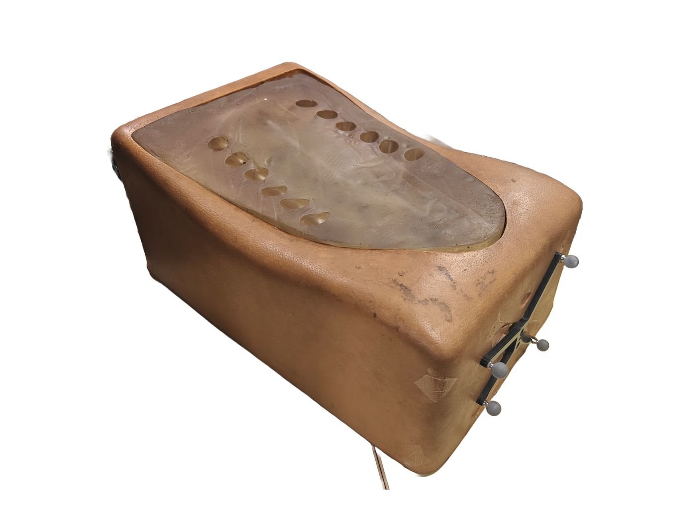
Closed Sawbone Phantom
Phantom Models. Left: Open Sawbone phantom. Right: Closed Sawbone phantom enclosed in soft tissue.

Experiments were divided into three groups: (1) Open Sawbone without distortion correction, (2) Open Sawbone with distortion correction, and (3) Closed Sawbone with distortion correction.

Group 1 serves as a baseline study where the registration is performed directly on open Sawbone phantom raw C-Arm fluoroscopic images where bone anatomy is clearly visible without any distortion correction. This evaluates the issues caused by uncorrected geometric distortions (Table 2a).

Group 2 uses the open Sawbone phantom across five different scenarios with distortion correction applied to assess how the distortion correction affects the registration accuracy (Table 2b).

Group 3 uses the closed Sawbone phantom, where the bone anatomy is fully enclosed by soft tissue, which attenuates the X-ray beam and degrades overall image contrast. This evaluates pipeline robustness under clinically realistic imaging conditions where fiducial visibility is reduced (Table 2c).

Table 2a — Registration accuracy: Open Sawbone, Without Distortion Correction
ScenarioAP Dist.LA Dist.Mean 3D Error (mm)Std. Dev. (mm)95% CI (mm)
1130 mm320 mm1.090.361.81
2150 mm350 mm1.030.351.73
3200 mm300 mm1.210.341.88
4150 mm200 mm1.440.302.03
5200 mm250 mm1.000.401.81
Mean1.150.351.85
Table 2b — Registration accuracy: Open Sawbone, With Distortion Correction
ScenarioAP Dist.LA Dist.Mean 3D Error (mm)Std. Dev. (mm)95% CI (mm)
1130 mm320 mm0.800.331.46
2150 mm350 mm0.940.331.61
3200 mm300 mm0.730.291.31
4150 mm200 mm0.810.361.52
5200 mm250 mm1.200.331.85
Mean0.900.331.55
Table 2c — Registration accuracy: Closed Sawbone, With Distortion Correction
ScenarioAP Dist.LA Dist.Mean 3D Error (mm)Std. Dev. (mm)95% CI (mm)
1130 mm320 mm0.360.160.69
2150 mm350 mm0.270.030.34
Mean0.320.100.51

3.3  Cadaveric Study

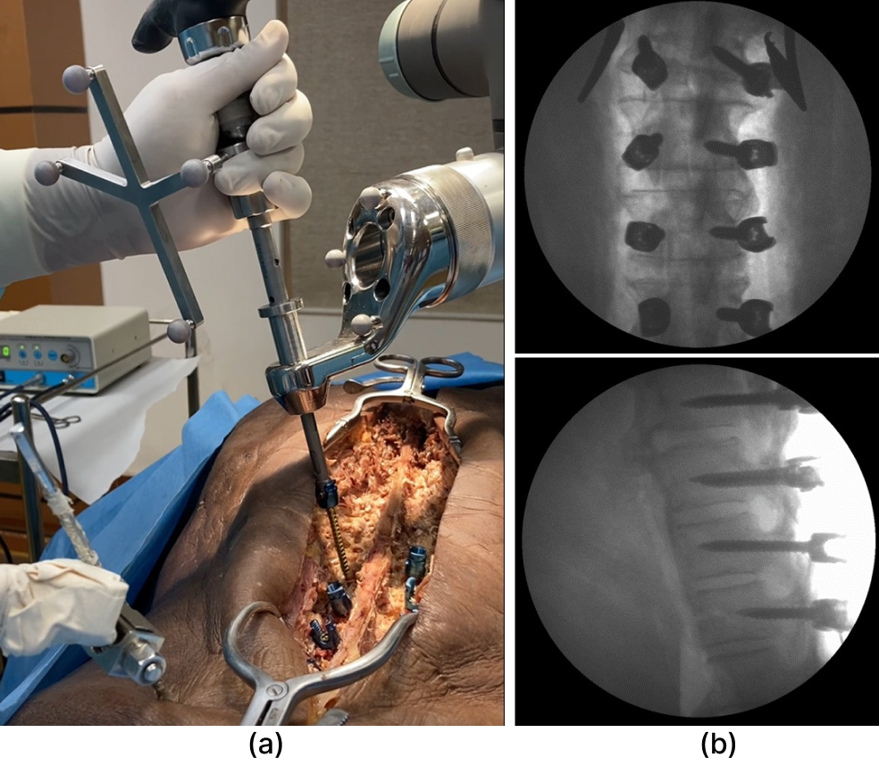
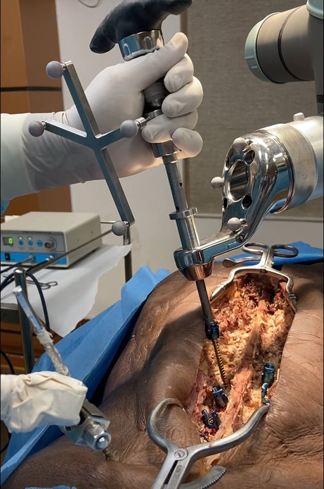
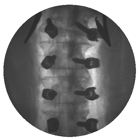
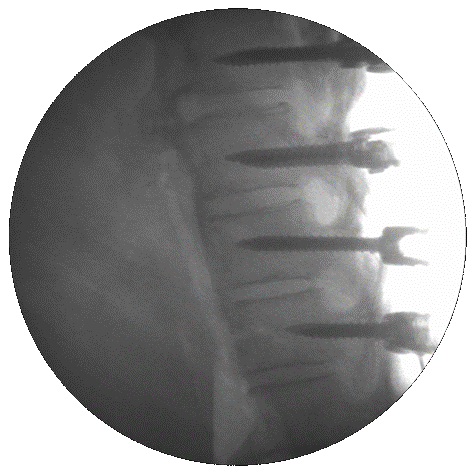
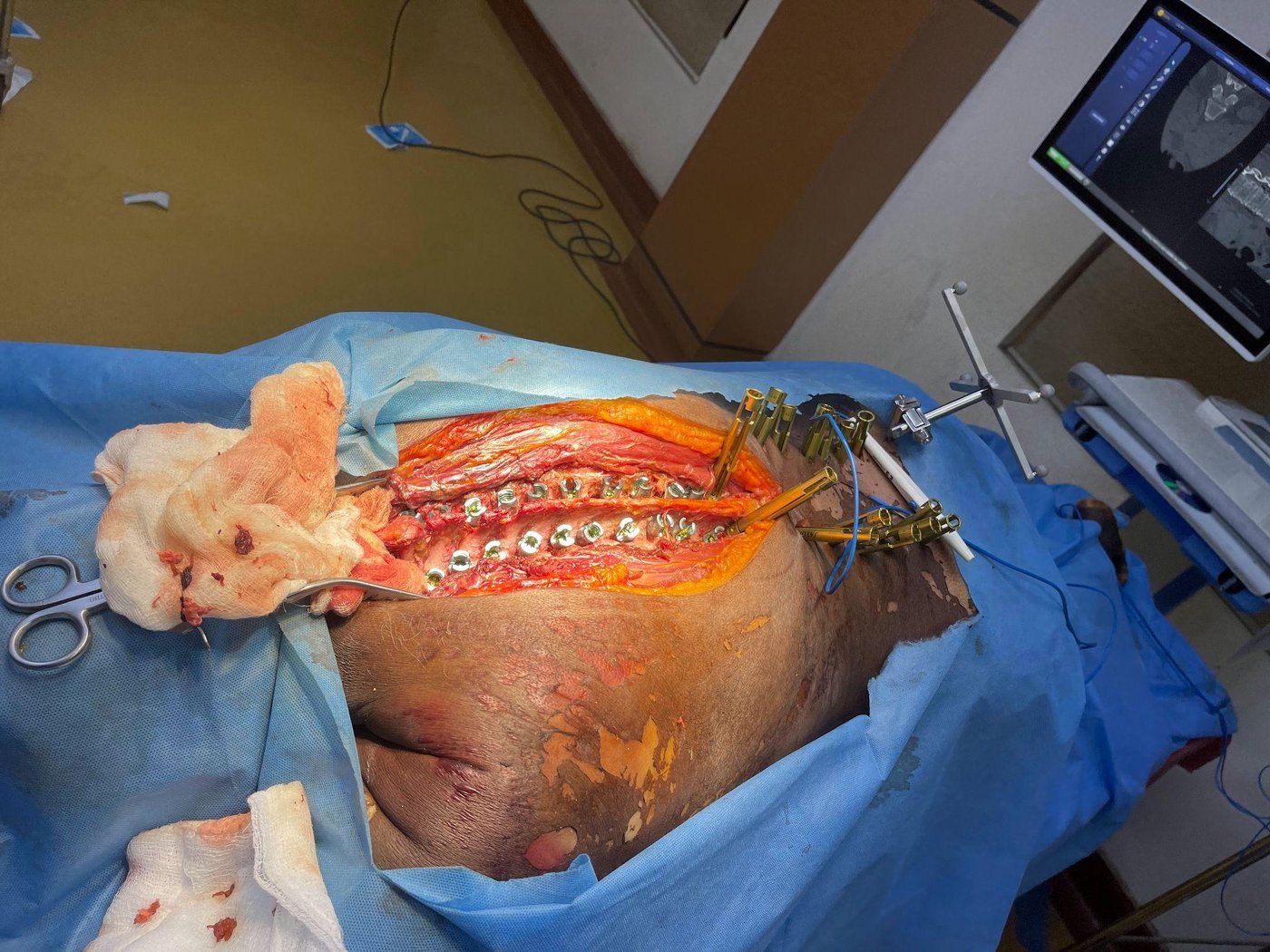
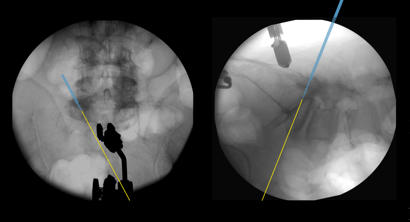
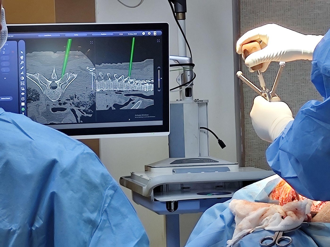
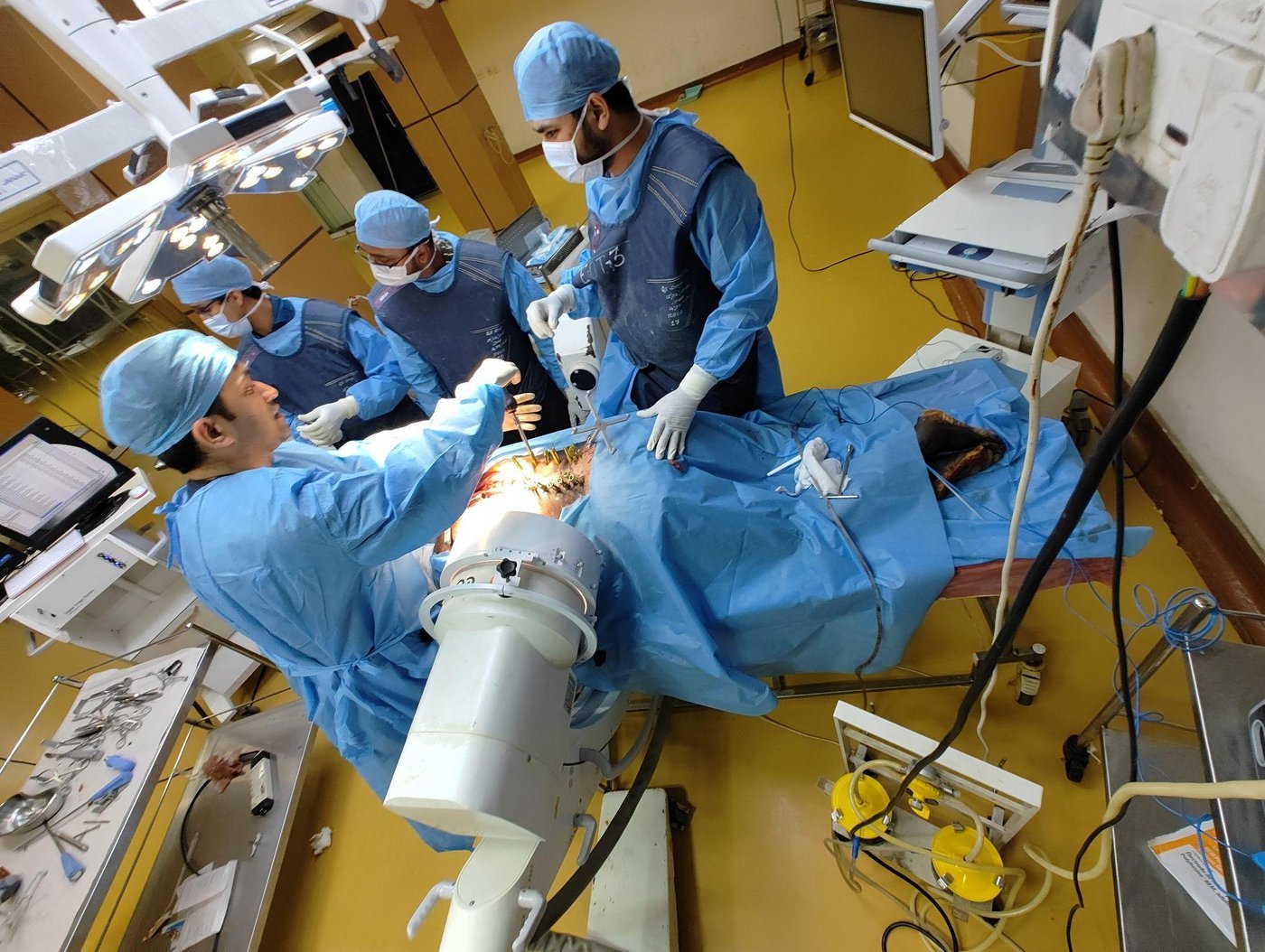
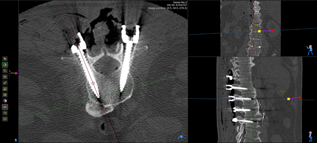
To validate clinical feasibility under realistic surgical conditions, a cadaveric evaluation spanning two specimens and two surgical techniques was conducted, illustrated in Fig. 6.

Cadaveric study setup and intraoperative verification
Fig. 6. (a) Open procedure setup. (b) Intraoperative lateral and AP fluoroscopic views.
Fig. 7(a) — GR-grade screw distribution by registration method
Cadaveric study, 50 screws total. A = 0 mm breach (best) · B < 2 mm · D < 6 mm · E > 6 mm
Landmark-based (96.5% A+B)
2D Fluoroscopic (90.5% A+B)
A · Landmark
26
A · 2D Fluoro
17
B · Landmark
2
B · 2D Fluoro
2
D · Landmark
0
D · 2D Fluoro
1
E · Landmark
1
E · 2D Fluoro
1
Fig. 7(b) — GR-grade screw distribution by surgical technique
Cadaveric study, 50 screws total. A = 0 mm breach (best) · B < 2 mm · D < 6 mm · E > 6 mm
Open (94.3% A+B)
MIS (93.3% A+B)
A · Open
32
A · MIS
11
B · Open
1
B · MIS
3
D · Open
1
D · MIS
0
E · Open
1
E · MIS
1

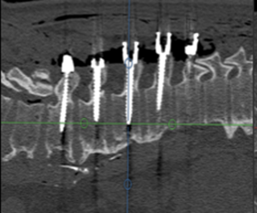
Two cadaveric specimens were instrumented at multiple thoracic and lumbar levels under both open and MISS approaches, with two user groups: surgeons with prior navigated experience (Group 1) and surgeons without prior experience (Group 2). All screws were independently graded post-operatively by CT on the GR scale. The proposed pipeline achieved a 90.47% overall acceptance rate versus 96.5% for landmark-based registration — clinically comparable, while eliminating pre-operative CT and time-consuming intraoperative manual landmark registration.

3.4  Patient Trials

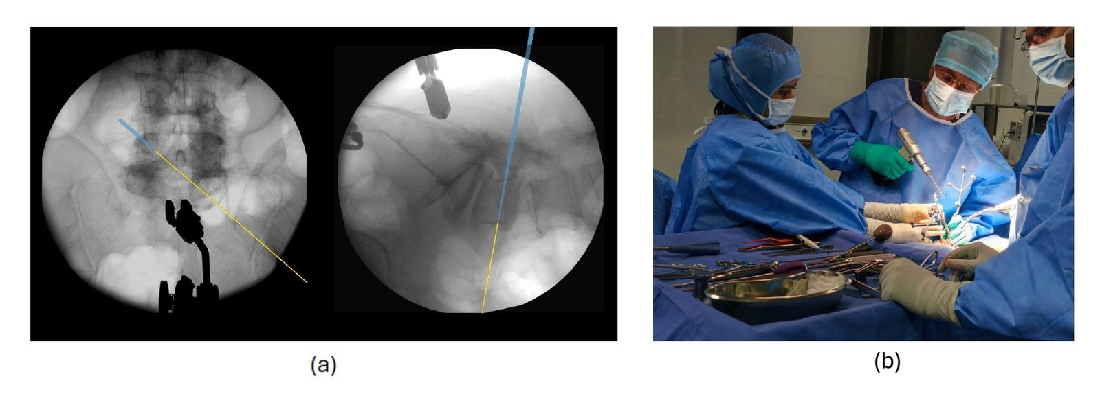
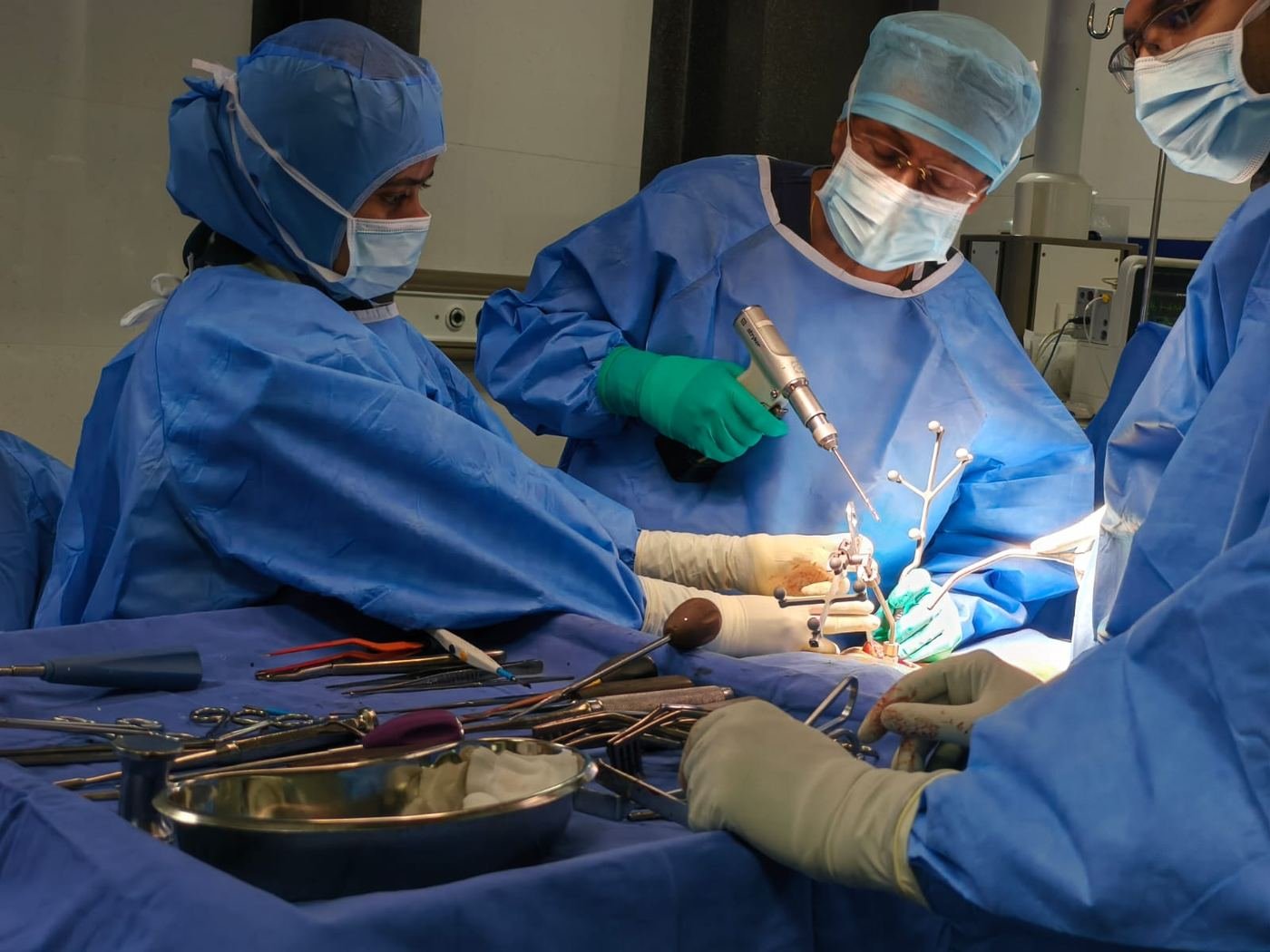
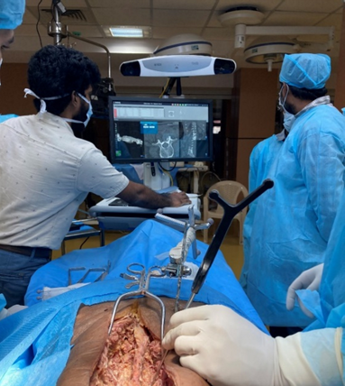
To further validate the system in a clinical environment, patient trials were conducted on 7 patients (4 deformity, 3 non-deformity). In total, 25 pedicle screws have been placed using the proposed registration to date (Fig. 8). Table 3 shows the overall composition of the patient cases along with their respective screw implantation rates in various spinal anatomy categories.

Live patient trial: tool tracking interface and surgical site
Fig. 8. (a) Real-time tool tracking interface. (b) Surgical site during a live clinical case.
Table 3 — Ongoing patient trials (as of 20 June 2026)
MetricOverallDeformityNon-deformity
Total Cases743
Total Screws25169
Cervical000
Thoracic202
Lumbar15105
Sacrum862
Summary

Conclusion & Future Work

This work proposed a fully automatic, device-agnostic 2D fluoroscopic image registration system anchored by a multi-faceted calibration drum with non-coplanar fiducials and a dedicated fiducial detection pipeline. Phantom and cadaveric validations demonstrated clinically acceptable registration accuracy, with a TRE below the 1 mm threshold required for accurate pedicle screw placement. Future work will focus on deep learning and template-matching-based fiducial recovery to address detection failures, along with large-scale patient trials for comprehensive clinical validation.
Team

Authors

Sandeep
Equal contribution
Healthcare Technology Innovation Centre, IIT Madras
Vishwanath Reddy B
Equal contribution
Healthcare Technology Innovation Centre, IIT Madras
Abhilash Chakkaravarthy
Equal contribution
Healthcare Technology Innovation Centre, IIT Madras
Vivek Maik
Healthcare Technology Innovation Centre, IIT Madras
Aparna Purayath
Healthcare Technology Innovation Centre, IIT Madras
Suhail Ansari T. A.
Healthcare Technology Innovation Centre, IIT Madras
Manojkumar Lakshmanan
Healthcare Technology Innovation Centre, IIT Madras
Mohanasankar Sivaprakasam
Corresponding author
IIT Madras · mohan@ee.iitm.ac.in
Citation

BibTeX

MICCAI CLIP 2026 — presented 1 October 2026, Strasbourg, France. Proceedings page numbers and DOI to be finalised at publication.

Cite this paper
@inproceedings{sandeep2026intraoperative,
  title     = {Intraoperative Fully Automatic Registration of Fluoroscopic Image Pair: Cadaveric Evaluation},
  author    = {Sandeep and {Vishwanath Reddy B} and {Abhilash Chakkaravarthy} and {Vivek Maik} and
               {Aparna Purayath} and {Suhail Ansari T. A.} and {Manojkumar Lakshmanan} and {Mohanasankar Sivaprakasam}},
  booktitle = {Clinical Image-Based Procedures (CLIP), MICCAI 2026 Workshop},
  year      = {2026},
  address   = {Strasbourg, France},
  month     = {October},
  organization = {Springer}
}
Bibliography

References

  1. Abdel-Aziz, Y.I., Karara, H.M.: Direct linear transformation from comparator coordinates into object space coordinates in close-range photogrammetry. Photogrammetric Engineering and Remote Sensing 81(2), 103–107 (1971), reprinted in PE&RS, 2015
  2. Ansari, T.A.S., Maik, V., Naheem, M., Ram, K., Lakshmanan, M., Sivaprakasam, M.: A hybrid-layered system for image-guided navigation and robot-assisted spine surgeries. In: 2024 IEEE/SICE International Symposium on System Integration (SII). pp. 1452–1457. IEEE (2024)
  3. Bertelsen, A., Garin-Muga, A., Echeverría, M., Gómez, E., Borro, D.: Distortion correction and calibration of intra-operative spine X-ray images using a constrained DLT algorithm. Computerized Medical Imaging and Graphics 38(7), 558–568 (2014)
  4. Besl, P.J., McKay, N.D.: A method for registration of 3-D shapes. IEEE Transactions on Pattern Analysis and Machine Intelligence 14(2), 239–256 (1992)
  5. Bott, O.J., Dresing, K., Wagner, M., Raab, B.W., Teistler, M.: Informatics in radiology: use of a C-arm fluoroscopy simulator to support orthopedic surgical training. RadioGraphics 31(3), E65–E75 (2011)
  6. Gertzbein, S.D., Robbins, S.E.: Accuracy of pedicular screw placement in vivo. Spine 15, 11–14 (1990)
  7. Gopalakrishnan, V., Dey, N., Golland, P.: Intraoperative 2d/3d image registration via differentiable x-ray rendering. In: 2024 IEEE/CVF CVPR. pp. 11662–11672 (2024)
  8. Grupp, R.B., Unberath, M., Gao, C., Hegeman, R.A., Murphy, R.J., Alexander, C.P., Otake, Y., McArthur, B.A., Armand, M., Taylor, R.H.: Automatic annotation of hip anatomy in fluoroscopy for robust and efficient 2D/3D registration. IJCARS 15(5), 759–769 (2020)
  9. Hartley, R., Zisserman, A.: Multiple View Geometry in Computer Vision. Cambridge University Press, 2nd edn. (2003)
  10. Heemeyer, F., Choudhary, A., Desai, J.P.: Pose-aware C-arm calibration and image distortion correction for guidewire tracking and image reconstruction. In: 2020 ISMR. pp. 181–187 (2020)
  11. Livyatan, H., Yaniv, Z., Joskowicz, L.: Gradient-based 2-D/3-D rigid registration of fluoroscopic X-ray to CT. IEEE Transactions on Medical Imaging 22(11), 1395–1406 (2003)
  12. Maik, V., Purayath, A., R, D., Lakshmanan, M., Sivaprakasam, M.: Gui-based pedicle screw planning on fluoroscopic images utilizing vertebral segmentation. In: 2024 IEEE MeMeA. pp. 1–6 (2024)
  13. Markelj, P., Tomaževič, D., Likar, B., Pernuš, F.: A review of 3D/2D registration methods for image-guided interventions. Medical Image Analysis 16(3), 642–661 (2012)
  14. P, Y.R., S, G., R, D., Purayath, A., Maik, V., Lakshmanan, M., Sivaprakasam, M.: Spine vision – x-ray image based gui planning of pedicle screws using enhanced yolov5 for vertebrae segmentation. In: 2024 EMBC. pp. 1–6 (2024)
  15. Parthasarathy, S., R, D., N, V., Maik, V., Purayath, A., Lakshmanan, M., Sivaprakasam, M.: Enpro: Enhancing precision through optimization in image-guided spine surgical procedures. In: Clinical Image-Based Procedures. pp. 42–52. Springer (2024)
  16. Purayath, A., Maik, V., Chakkaravarthy, A., Lakshmanan, M., Sivaprakasam, M.: A novel Spatio²-Frequency blob detection algorithm for enhancing precision in image guided surgery. In: 2024 IEEE MeMeA. pp. 1–6 (2024)
  17. Sommer, F., Goldberg, J.L., McGrath, J.L., Kirnaz, S., Medary, B., Härtl, R.: Image guidance in spinal surgery: a critical appraisal and future directions. International Journal of Spine Surgery 15(s2), S74–S86 (2021)
  18. Yaniv, Z., Joskowicz, L.: Long bone panoramas from fluoroscopic X-ray images. IEEE Transactions on Medical Imaging 23(1), 26–35 (2004)
  19. Zheng, G., Zhang, X.: Robust automatic detection and removal of fiducial projections in fluoroscopy images: an integrated solution. Medical Engineering & Physics 31(5), 571–580 (2009)